Mechanical Screen Strength & Weld Separation Testing
The laboratory conducts complex strength downhole screen testing. This testing is conducted in the set of benches used for various mechanical stress testing arising during equipment usage.
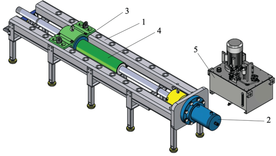
The main mechanical testing bench is a MPF-100 (Mechanical Power Frame) bench for axial loads used for screen construction tensile/compression (force up to 100 tons) testing.
The mechanical bench is used for downhole sand screens testing based on API 19SS (2016), ISO 17824:2009, GOST 32504–2013– Petroleum and natural gas industries-Downhole equipment-Sand screens, except pre-pack screens. To test the working capacities with applied loads, the testing process simulates sand screen components with operational loads.
MPF-100 Bench Specifications:
- Bench outline dimensions (L x W x H) – 4,850 х 680 х 1,060 mm;
- Bench weight – 2,150 kg;
- Piston stroke – 200 mm;
- The length of the sample screen is from 1,000 to 10,000 mm;
- The size of the testing screen sample is from 4 to 7″;
- Highest cylinder rod load (extension and retraction) – 100 tons.
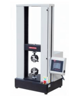
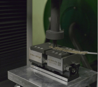
The MBM-1 (Mechanical Breaking Machine) with a force capability up to 1 ton is used for the wire separation testing. Special equipment is used for the testing process. The speed of punch movement from 0.01 mm/min to 500 mm/min and the wire separation moment are set with the mechanical press.
Description of the Main Types of Mechanical Testing:
1. Pull Test, Push off Test, End Ring Push off Test, Supporting screen elements push
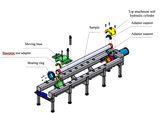
Testing Performed on the MPF-100 Multifunctional Testing Bench. The primary objective of testing performed on the MPF-100 multifunctional testing bench is to determine the mechanical strength of downhole screens subjected to axial loads as per their declared specifications. The testing bench comprises a support frame, a two-way hydraulic cylinder for axial loads, mechanical fasteners adapters for the screen, and a control system for the bench. A sample of the screen being tested is fixed onto the load frame for conducting the tests.
During testing, the screen sample is subjected to axial loads, which necessitates a secure fixation of the sample to the load frame, as well as to the hydraulic cylinder rod.
Testing is performed by the following programs:
- Push off testing (wrap-on-pipe screen);
- Retaining ring push off testing;
- Shrouded screen or cemented winding push off;
- Perforated basepipe pull push.
Testing procedure:
- Testing plan, which includes:
– Type of performed testing;
– Maximum axial force applied on the sample;
– Allowable construction elements push values and slot clearances changes;
– Quantity of the sample testing repetitions. - The sample is cemented at the screen element field up to 1,500 mm in length, screen sample surface must be fastened to avoid the contact with screen basepipe;
- During the shear testing, the support screen elements of the screen wire wrap are examined for the shear of the wire wrap section, which measures 304.4 mm in length, as well as the length of the basepipe screen sample, which is 1000 mm;
- The mechanical adapters for fixation on the load frame of the stand are selected for the sample. The slot clearances of the testing screen element are preliminarily measured;
- An axial load is applied to the sample and it is increased according to the specified speed. The testing process ends when the target force is reached and the load is held for one minute. The testing procedure is repeated, if necessary;
- At the end of the test procedure, the load is shed, the screen sample is released from the fasteners, and the visual inspection of the sample and re-measurement of the slot clearances in the marked areas are performed;
- The force and rod position of the hydraulic cylinder as a function of time is recorded in the electronic journal. At the end of the test, the results are analyzed and the report is generated.
The MPF-100 mechanical testing bench is certified and calibrated by independent certification authorities.
Mechanical Wire Wrap Separation Testing (Weld Separation Test)
The MBM-1 bench is used for wire wrap separation testing, also known as weld separation test. It aims to determine the mechanical strength of the welds in wire wrap screens. The testing process involves using rectangular wire wrap coupons that are cut from the screen. A mechanical press punch movement is used to produce separation force to the wire wrap from the guide rods. The strength of the wire screen weld is measured by the value of this force.
The wire wrap separation testing bench is designed to withstand loads of up to 10 kN. For manufacturers, the direct screen wrap’s validity criterion is that the welded wire connection and stiffeners should not split at a tensile load of at least 1.23 kN (125 kgf).
Testing procedure:
- Rectangular-shaped wire wrap coupons are cut from the wire wrap screen, at least 50 mm x 150 mm in size. At least two coupons, taken from different areas of the screen element, are used for testing;
- Testing is performed when the coupon sample is placed on the bench and the press punch produces the force on the wire separation from the guides;
- Testing is performed for the individual coils of the wrap until it is separated from the guides. At this point, the separation moment is recorded. Each coupon is tested at least 3 times. The series of testing determine the average force values;
- The test is completed if the average force values are higher than 1.23 kN;
- The report is drawn up based on the testing results.
The wire wrap separation test bench is regularly checked for accuracy and calibration of the generated forces. Wire wrap separation testing is part of comprehensive mechanical strength screen testing.
Mechanical Screen Torsion Testing (Torsion Test)
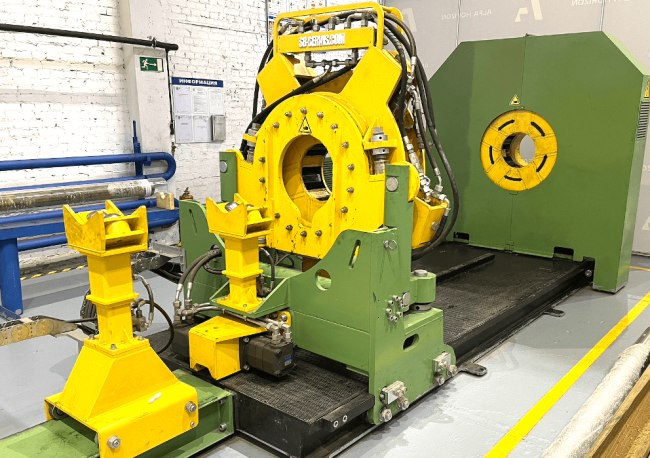
The purpose of testing is to determine the mechanical strength of the screen under torsional loads, with the liner rotating alongside the screen. In this case, the MTM-80 bench is used for testing.
Hydraulic wrench bench is utilized for testing, primarily designed for coupling installation on the nipple section of the base pipe. It controls the force torque applied to the support foot of the screen base pipe end holder, rotating around the sample axis. The screen in the second wheelbarrow is secured to the cemented part of the screen element. The practical validity criterion is to withstand a nominal torsional torque of 25 kN·m by the screen.
Testing procedure:
- Prepare the screen sample for the torsion testing. Cement the screen part according to the pull/push test procedure;
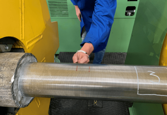
- After that, the screen sample is placed on the stand of the hydraulic wrench to fix the cemented part of the screen and the end of the base pipe. Conduct a test measurement of the slot clearance of the testing part of the screen by three selected areas arranged with a rotation of 120 degrees with respect to each other around the screen axis;
- Torque force is applied to the mechanical foot in the testing mode. Increase the load gradually up to the limit value for this test. Repeat the testing process after the load is released, if a series of tests is provided;
- A visual inspection of the screen sample is performed during the tests. The operator is in the remote control area of the test bench. The load is shed on the sample when the force moment limit is reached. The stand is switched to idle mode. The screen slot clearances in the designated areas are re-checked;
- Based on the results of the tests, the validity report of the screen torsional loads is drawn up.
Mechanical Screen Bending Tests (Bending Test)
The purpose of this testing is to verify the mechanical strength of the screen against bending loads. A downhole liner is composed of various components and must be able to flex due to the spatial curvature of the well’s drilled trajectory. To evaluate the screen’s ability to withstand bending loads, specific tests are conducted.
To perform bend testing, screen supports, weighting agents, laser levels, and leveling rods are utilized. The screen sample is bent in a circular shape, and the minimum requirement for the screen to sustain the bend is 45 degrees over a length of 30.3 meters (100 ft).
Bending testing must be repeated at least 10 times, and the screen must retain its characteristics after testing. The slot clearances should not change by more than 5%, and the quality of the welds must be maintained.
Testing procedure:
- The screen sample should be placed on supports of equal height to give enough room for the screen and the supports for bending testing. Two areas of the sample are examined:
– The middle part of the screen;
– Part of the screen with an ending ring in the center. - Conduct a test measurement of the slot clearance of the testing part of the screen by three selected areas arranged with a rotation of 120 degrees with respect to each other around the screen axis;
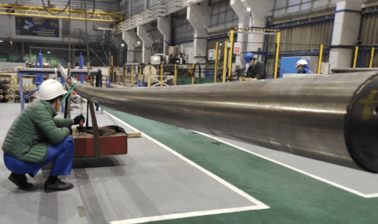
- The screen supports should be levelled to ensure that they are all in the same horizontal plane. The central portion of the screen sample between the supports is suspended from a crane beam using slings. A weighting agent is then attached to the sample at the center of the testing area. The degree of deflection of the screen area under test is measured using a leveling rod and a laser level;
- The center of the screen testing area is slowly lowered by the crane beam with the weighting agent. The screen sample deflects. The metric tools are used to record the amount of deflection. The calculated value of the minimum deflection must be reproduced during the test. The process is halted when the required deflection value is reached, then the sample shape is gradually restored by lifting the crane beam. Testing is repeated at least 10 times for each testing area;
- Once the testing series is completed, a slot clearance control measurement is performed at the designated areas of the sample. The test is deemed successful when the deflections resulting from the applied load are within the permissible limits.

