Downhole Hydraulic Testing

HFL-150 Hydraulic Bench

Hydraulic testing is a critical area in determining the quality of downhole equipment. This downhole equipment testing assesses vital characteristics such as the collapse and tensile strength, erosion resistance, and discharge behavior of inflow control valves. The HFL-150 hydraulic circuit bench is the primary testing device used for these purposes.

The hydraulic bench specifications:

  • The hydraulic circuit maximum pressure is 170 atm (~2500 psi)
  • The working fluid viscosity is up to 1,500 cP;
  • Concentration of solid abrasive (sand form) (SSC) up to 1% (10,000 ppmw);
  • The working fluid temperature is 10 – 600 °C;
  • The maximum abrasive particle size is 500 microns;
  • Maximum circuit flow rate 50 l/min (3 m3/h) at 140 bars;
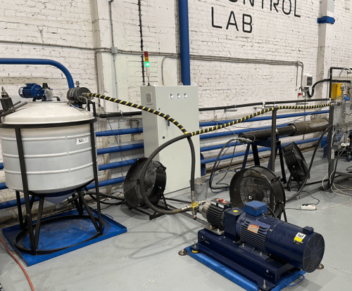
  • Conical vessel with a stirrer (working fluid for 0.5 m3);
  • The test capsule for the screen sample is 4 ½” and the outer diameter of the winding is 130 mm. The working capsule’s outer diameter is 168 mm;
  • Bench automation system includes:
    • Frequency converter (inverter) of a hydraulic pump;
    • Cooling control system;
    • Emergency control system.
  • The parameter registration system includes:
    • Inlet and outlet capsule pressures;
    • Mass circuit fluid rate;
    • Fluid density;
    • Fluid temperature;
    • Fluid level in the storage tank.
HFL-150 Hydraulic Bench

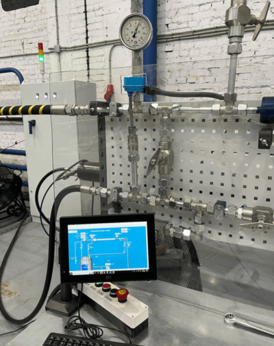
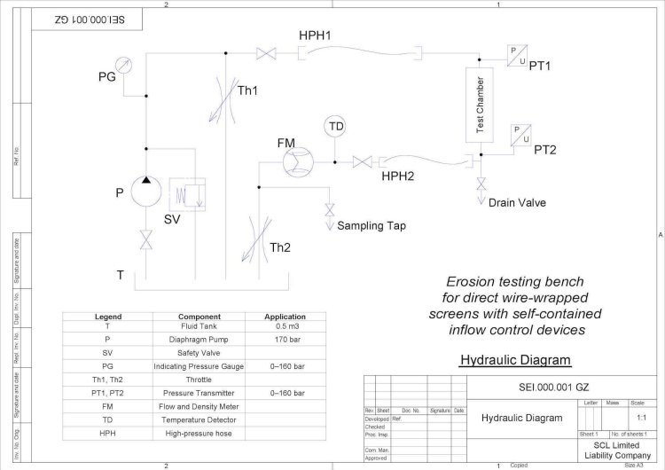
The hydraulic bench design incorporates a hydraulic suspension pump, a testing capsule for the sample being tested, a conical tank, a Coriolis flow meter, pressure and temperature sensors, hydraulic throttles, RVD, fittings, shut-off valves, and an automation system. The continuous flow of working fluid through the circuit enables tests to be conducted over multiple days.

A modification of the HFL-150 hydraulic circuit bench enables collapse/tensile sand screen testing.

Flow Performance Tests

Flow performance testing is crucial in determining the flow rate specifications of inflow control devices. This test is conducted using fluids of varying viscosity values, and the HFL-150 hydraulic circuit bench is utilized for this purpose. Typically, testing is performed using water and oil with a given dynamic viscosity value, in accordance with API Specification 19SS, 2019.

Controlling the temperature of the fluid in the hydraulic circuit is critical, as the fluid viscosity is highly temperature-dependent. Flow performance testing assesses the pressure drop of the testing sample and the total inlet pressure level in the test capsule. The resulting flow curves are constructed based on the pressure drop and vary depending on the fluid’s viscosity.

Testing Procedure:

  • Installing the testing capsule;
  • Assembling hydraulic connections;
  • Filling the hydraulic system with the working fluid;
  • Checking all connections for leaks;
  • Removing air from the hydraulic circuit;
  • Setting the working limits for control system parameters. An emergency situation is considered to occur when the values exceed the working limits. In such cases, the testing bench should be immediately shut down. The working limits have the following characteristics:
    • The minimum fluid level in the conical tank;
    • Pressure drop limits;
    • Mass flow rate value limits;
    • Fluid temperature limits. When the upper value of the limit is reached, the circuit cooling system is activated, when the lower value is reached, it is deactivated.
  • Adjusting the pump speed and the needle valves (throttles) to achieve the required pressure difference at the inlet/outlet of the testing capsule;
  • Starting and running testing;
  • Analyzing the accumulated data on the sensor readings, data graphing, and generating a testing report at the end of testing.

Hydraulic Erosion Testing

The objective of this testing to verify the resistance of sand screens, control valves, and injection valves to erosive wear and determine their feasibility for use in challenging oil and gas field conditions. The erosion testing task implies the following actions:

• To conduct testing following API Specification 19SS, 2019 quality standards;
• To determine the operation possibility of downhole screens and BOP and injection valves at hydrocarbon resource development facilities;
• To verify the erosion resistance of downhole screens and BOP and injection valves;
• To decide on supply equipment for serial production following the results of testing.

Erosion testing on the HFL-150 Bench

To create an erosion environment, abrasive (sand-laden) particles are added to the working fluid at a desired concentration. The testing process is designed to simulate the conditions of long-term use of the equipment in a well, and therefore is performed over an extended period of time. The duration of testing is dependent on the options of abrasive concentration in the working fluid.

We adhere to the recommendations set forth in the API Specification 19ICD for Inflow Control Devices (2019). The methodology for erosion testing involves conducting flow performance testing both before and after the erosion test. This allows for the evaluation of the effects of erosion wear on the testing assembly by measuring the flow characteristics of the valve during flow performance testing.

For erosion testing, additional operations are added to the flow performance testing procedure. These are

• To add abrasive in the concentration according to the test specification;
• The testing process is halted when either the scheduled testing is completed or when the system parameters deviate from the specified range. Any deviation of pressure and flow parameters beyond the set limits is considered an erosion valve failure.

To assess the impact of erosion on the valve weight, the testing valve should be weighed before and after removal from the device. Additionally, the valve’s condition should be photographed and analyzed before and after testing.

Hydraulic Collapse Tensile Testing (Burst&Collapse Test)

The objective of this testing is to verify the resistance of sand screeners, and control and injection valves to erosive wear and the exploitation possibility in difficult oil and gas field conditions. The erosion testing task implies the following actions:

• To conduct testing following API Specification 19SS, 2019 quality standards;
• To determine the operation possibility of downhole screens and BOP and injection valves at hydrocarbon resource development facilities;
• To verify the erosion resistance of downhole screens and BOP and injection valves;
• To decide on supply equipment for serial production following the results of the testing.

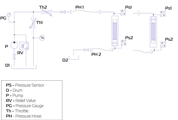
Hydraulic diagram of the burst/collapse testing

The strength of the sand screen construction is tested beyond just mechanical tests. It is necessary to determine the sand screen strength in downhole conditions, including under large pressure differentials. Hydraulic tests are conducted to determine screen structure burst and collapse, using a modified HFL-150 hydraulic bench. For the test, two colmatant tanks are used, and the testing screen sample is placed in a special testing capsule of large size (273 mm outer diameter). The hydraulic bench scheme employs an open circuit for the fluid.

A specialized technical liquid formula solution is selected for colmatizating the screen sample in the high-pressure test capsule. The solution must be well mixed and contain calcium carbonate with particle size fractions, xanthan gum, and starch to create a highly viscous medium. The screen with the solution under pressure in the testing capsule is colmatized. The main objective of testing is to check the screen strength at high burst/collapse pressures with a colmatized solution.

The mini hydraulic laboratory bench is used to prepare the required solution. It verifies the colmatation properties of the solution through a wire-wrap screen coupon.

The hydraulic bench is a versatile piece of equipment that can be used in two configurations, with flexible supply hoses connecting it to the testing sample. For the bursting testing, pressure is applied inside the borehole screen sample, while for the collapse testing, pressure is applied to the outside of the testing sample. Prior to the hydraulic testing, preparatory work is necessary to build up a reserve of colmatated fluid and to install the screen sample on the test bench. The test is performed in accordance with API Specification 19SS, 2019 and the results confirm the screen’s strength parameters under high-pressure conditions.

Testing procedure:

  • To prepare the testing colmatation solution according to the basic formulation;
  • To test the colmatation properties of the solution on a mini-bench based on the testing screen wire-wrap coupons. To change the solution formulation to achieve the required characteristics;
  • To prepare the required volume of the colmatation solution according to the developed formulation;
  • To prepare the testing screen sample;
  • To install the sample in the working capsule of the bench;
  • To mount the connecting hoses of the bench. To fill the colmatant tank;
  • To connect the hydraulic slurry pump to the bench;
  • To start the test program. To increase slowly the pressure in the chamber to the target values. To register the different points of pressure values of the hydraulic circuit and the colmatant flow rate;
  • When the maximum pressure of the test program is reached or if there is a breakdown in the testing screen, the test process should be halted and the system should be depressurized;
  • The result is the conclusion of the hydraulic testing.

The hydraulic bench specifications:

  • Max working pressure is up to 200 atmospheres;
  • The capsule length – 4,000 mm;
  • Capsule diameter – 273 mm;
  • Capsule weight – 3,550 kg;
  • Screen sizes – 4 ½; 5; 5 ½; 6 ⅝; 7″;
  • Maximum system flow rate – 2.8 m3/h.

The operator conducts all the necessary hydraulic tests in the protected area located in the bench control system.

You may also be interested in other categories

This site uses cookies to store data. 
By continuing to use the site, you consent to the use of these cookies.

This site uses cookies to store data. 
By continuing to use the site, you consent to the use of these cookies.